Gm Iac Wiring Diagram
Car or truck needs a new knock sensor and wiring harness then it probably needs the throttle body and IAC valve cleaned as well. Knock Sensor Wiring Harness.

Wiring Diagram Ls1 Engine
As a result five additional connections are made at the DB37 connector.

Gm Iac Wiring Diagram. Chevy 350 tbi stalls when warm. Ford didnt begin to use ETC until a PCM could be developed with enough processing speed to handle ETC functions. Holley carburetors have powered every NASCAR Sprint Cup team and nearly every NHRA ProStock champion for four decades.
Its both useful and empowering to know how to fix your own car. Car Maintenance Repairs How-Tos. Prev 1 2 May 10 2011 Re.
I should have remembered. Coolant Temp sensor ECT 9. Take control of your LS engine with Terminator X Max.
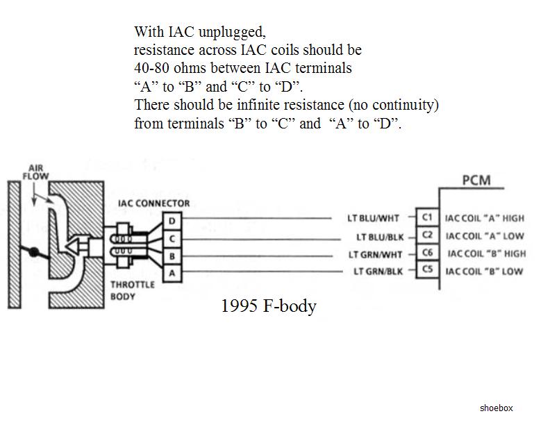
Idle Air Control Motor IAC 3. Below the second cylinder. Intake Air Temp Sensor IAT 12.
The Idle Air Control Valve is located under the intake manifold. Third it must be Pin-Mapped to an available J1 connector output pin. When using factory computers and wiring pay close attention to the connectors.
I prefer it to be a ground output however it can be programmed to be either one 12V or ground. Throttle Position Sensor TPS 6. When GM first began using the ETC system in their 2000 model year the PCM couldnt process APPThrottle Control data fast enough and so a stand-alone module was used.
IAC Idle Air Control Fuel Pump Relay ALDL Diagnostics Connector Crank Signal Fuel Injector SES Service Engine Soon Light Fuel Injector Control Module Coil Distributor First the big picture block diagram. If your LS V-8 powered General Motors Corp. Ford frequently changed them even within model years.
Mercathode System Wiring Diagram INDEX GASOLINE ENGINES BRAVO MODELS MerCathode System Wiring Diagram BLK BLACK BLU BLUE BRN BROWN GRY GRAY GRN GREEN ORN ORANGE PNK PINK PUR PURPLE RED. Whether you need to test the condition of your car battery fix your AC or simply change your tires learn how with these step-by-step tutorials. Terminator X Max features real-time fuel learn high impedance injector drivers an integrated 1bar MAP sensor.
It had a lot of dirt in it. Now Holley EFI is dominating the performance world as well as our products for GMs LS engine. MAP sensor 31L 34L Serpentine Belt Routing Diagram.
Optispark vacuum harness GM pn 12555323 vacuum fitting GM pn 14082470 or tee to provide vacuum for the opti 95 or later timing set components or at least the cam gear cam gear GM pn 10206039 crank gear GM pn 10128346 chain GM pn 10128485 timing cover gasket GM pn 10128293 water pump gaskets 2 GM pn 10128343. Diagnosis Clean the dirty Idle Air Control Valve IAC. The ground may be a chassis ground on a certain com ponent such as an alternator or a starter or a wire.
Ford Generic Ford PID List plus Image Locate identify which fuse or relay is blown it may be located under dash under hood in trunk find the. 1988 350 TBI idles funny stalls when put in gear and accels rough Fixed. Click View Outputs on the Pin Map.
Mass Airflow sensor MAF 4. 4 10 INTRODUCTION Holley Performance Products has written this manual for the installation of the TERMINATOR X MPFI fuel injection systemThis manual contains the information necessary for the installation of the hardware contained in this kit which includes the ECU wiring and 35 touch. 1 First Enable the Electric Fans in Basic IO - System Parameters.
After rebuilding the fuel pressure regulator new fuel filter plugs and wires I finally dropped a new fuel pump in and seems to be running like a champ. Wiring Repair 14 Special Tools 15 VEHICLE SECTION RV Models A-1 P Chassis B-1 WIRING DIAGRAMS 2 DESCRIPTION Figure 1Wire Coding The diagrams are to be traced from the source of electricity the battery positive post to ground. However the newer the engine and vehicle the more difficult it is to use the factory components.
The car did not start at ALL. If you are using a V3 main board use this wiring diagram External Wiring with a V30 Main Board. 558-406 GM Drive By Wire Harness Complete terminated harness with J3 connector to operate late GM drive by wire systems.
Second enter InputsOutputs also in System Parameters and select the Output Type for Electric Fans. Ford Wiring and Connectors. Of course you should replace the intake manifold gasket and clean all of the parts.
General Motors MAP sensors are suitable Pin24 connects to pin B on the sensor pin A is grounded pin C gets 5 Volts from Vref Pin28 on MicroSquirt. You can also use the original MPX4250 MAP sensor used with MegaSquirt you connect the pion 24 to the sensors Pin1 Pin2 is grounded and 5 Volts Vref is connected to pin3. GM LS Engines with 58x Crank 4x Cam - 485360 Truck Engines and LS2LS3 - EV6 Injector Harness 35 Touchscreen Included Part 550-905 Be the first to write a.
Dont settle for a junkyard ECU with a cumbersome tuning interface when you can have complete control of your engine self-learning fuel strategies and the proven race-winning technology of Holley EFI at a budget-friendly price. Because of the added stepper IAC ignition control and PWM idle capabilities of the MegaSquirt-II the V30 main board has been designed with these functions in mind. Using Ford factory wiring harnesses is an option for most engines and projects.
Evap Purge Solenoid 10. 558-408 J2A J2B J3 J4 Connector and Pin Kit Contains connectors and pins but no wiring. So I took out removed the two hoses and cleaned it by spraying it with engine grease remover.
The components you will see on the left are sensors. Holley has been the undisputed leader in fuel systems for over 100 years.
Stealth 316 Isc Servo Motro

Zl 3973 Corvette Lt1 Engine Diagram Lt1 Idle Air Control Valve Location Chevy Wiring Diagram

Need Wiring Schematic Image For 1999 2002 Oldsmobile 3 5 Dohc Iac Valve Wiring And Terminal Identification

Sh 3217 Gm Tbi Iac Wiring Diagram Wiring Diagram
Correct Wiring For 1992 Idle Air Valve Pigtail Corvetteforum Chevrolet Corvette Forum Discussion

Cold Start Options For Efi Pelican Parts Forums


Aem Infinity 6 Gm Iac Stepper Motor Wiring Pinout Pins Polarity Aem

Do You Have The Wiring Schematic For An 87 94 Chevy Need The Wiring Diagram For The Idle Air Control Valve
Assembly Instructions For The Iac Pigtail Piggy Diyautotune Com
Diagram 2008 Gmc Wiring Diagram Accelerator Full Version Hd Quality Diagram Accelerator Dodiagram Aitrearchivenezia It

Diagram 1998 Toyota Rav 4 Idle Air Control Valve Wire Diagram Full Version Hd Quality Wire Diagram Diagramsys Aitrearchivenezia It

Iac Count And Different Mfg Iac Motors Same Same The Bangshift Com Forums
4th Gen Lt1 F Body Tech Aids
Dbw To Dbc Conversion 03 Harnesses
Wiring And Configuring Outputs On Different Types Of Idle Actuators Us Adaptronic

Gm Iac Or Intake Stopper Motor Rx7club Com Mazda Rx7 Forum
Gm Corvette 1984 1996 Idle Air Control Valve Repair Guide Autozone

Holley Performance Products Forums

Idle Valves How To Wire Them How To Set Up The Aux Outputs In The Ecu Youtube


Comments
Post a Comment